OF SOUTH AUSTRALIA INC
Smiths Pin Clock Polarity Change
Commentary by Grant Rodman,
Jaguar Car Club of Tasmania
OF SOUTH AUSTRALIA INC
OF SOUTH AUSTRALIA INC |
Smiths Pin Clock Polarity Change Commentary by Grant Rodman, Jaguar Car Club of Tasmania |
OF SOUTH AUSTRALIA INC |
Early Jaguars have Positive Earth electrics. This in itself is not a problem, unless you want to fit some modern gizmo that requires a negative earth.
The original Valve radio and the clock are components that are polarity sensitive, so are usually left disconnected (sometimes the fuel pump/s also has to be modified) quite often it is the fitting of a new stereo that is the reason for the polarity change in the first place. In my case I had fitted a mapped electronic ignition system for an advance curve better suited to unleaded fuel.
I had already figured how to change the old valve radio to negative earth, so that left the clock I couldnt resist the challenge. (Heh the worst that could happen is I have a clock that doesnt work again!). Intrigued with an article by Graham Robinson of the Hillman Owners Club of Australia on other Smiths pin clocks, I discovered by simply reversing the rectifier and coil leads, the clock is converted to negative earth.
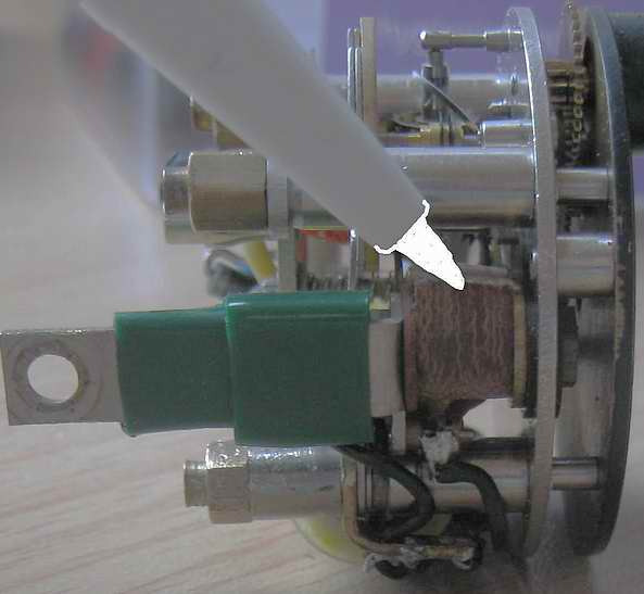
Here is where the rectifier is originally located which could be either a cylindrical unit, or a
disk & spring type if its still serviceable the cylinder or disk can simply be turned over and
popped back in, swap the leads to the coil and Bobs your uncle!
It would be prudent at this point to drop it into a watch maker for a clean and oil clock oil is a special formulation and if not applied correctly can wick out and leave the pivots dry.
WARNING: Take great care when handling the clock when its out of the case, as the balance wheel and hair spring are partially exposed and easily knocked. The hair spring is closely matched to the balance (I believe its called vibrated) so damage to either could ruin the clock. One of many lessons I learnt the hard way!
I chose to replace my rectifier with a modern power diode as it had deteriorated and caused the tip of the spring contact to burn off, due to the high EMF from the coil (which can be many, many volts). This particular clock required the fitting of a small insulated block to replace the old cylindrical rectifier, I then set about replacing the burnt contacts (not something I recommend or want to do again!) and getting the clock operational and keeping reasonable time. Keep in mind changing battery voltage and temperature will also affect accuracy (another lesson learnt the hard way!).
I then chose to go another step and look at a way to extend the life of the delicate contact arrangement which is prone to fouling (these are the bits that get fried if connected to the wrong polarity, due to having no fuse and a dead short through the rectifier diode).
After discussing various options (and lessons about basic electronics) with our electronics wizard at work, I chose to try a simple transistor arrangement that would still use the original contacts (but switching only 1½ milliamps instead of 15) and also something that I could comfortably build myself (thus so can anyone else!). Anything more complex would require tiny surface mount components which would test my shaky fingers & failing eyesight Scotch helps with the shake but wreaks havoc with the eyesight!
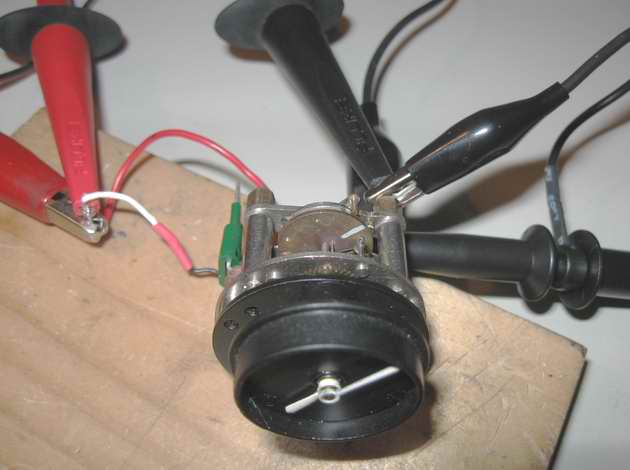
This clock out of my 1960 Mk2 has a Brysons part number #21757 on its case, so I suspect it
may have been replaced earlier in the cars history. In this photo it is connected to an
oscilloscope (boy! Is that a neat toy?) to see what the impulses were doing at various stages of
the project (looks like its on life support dont it? the number of times I bumped, dropped &
bent bits during the project the poor thing should be in an iron lung by now!). The white
mark on the balance wheel in-line with the pin makes it easy to see how far the balance is
oscillating, and even though the scope gave much insight about the signal & pulse shapes, it was
this little white line that became the most important reference point.
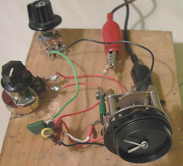
Now the transistor is connected temporarily to test its operation & fine tuning I used some
small pots in place of the resistors to confirm my calculations (remember I have limited skills in
these fields the main rule in my shed is to always have a bigger hammer at the ready!).
Immediately the balance wheel increased its swing & speed, so to dampen it a bit I added a
capacitor/resistor combination to the base side of the transistor, eventually settling on a 0.1µF
capacitor & 20 kΩ resistor. My logic was to use similar size resistors so the current through
the contacts is still minimal, but this resistor value may vary clock to clock because of
Balance/hair spring, and capacitor/resistor tolerance variations. This particular clock likes
the balance to oscillate about 540° too little, it will stall easily, too much and the scroll
ends hit the escapement teeth. I tried to get its consistency as close as possible before
final assembly so the last bit of fine tuning could be done with its own regulating pins. End
result was about +- 2 minutes a week.
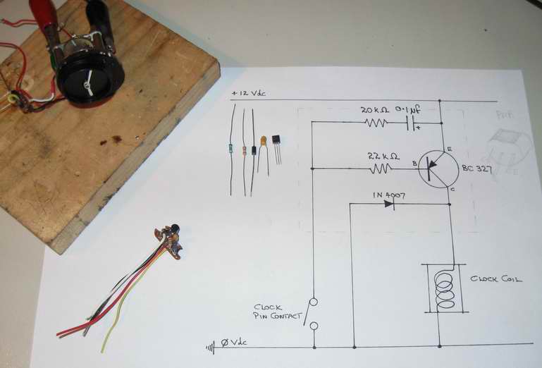
Diagram, components and finished circuit ready to fit. There is not a lot of room in the
case, so I chose to put this lot on a small circuit board to fit in a small space off to the side
of the coil, but I also built another one with the components layered & wrapped in shrink tubing
so it could snake around the gear train under the coil.
Its not a bad idea to put an inline fuse in the power lead when refitting the clock back in the dash to protect all that hard work 250mA is ample.
Material List
In Conclusion
I have no doubt there are better ways to build a more reliable and accurate time piece, but the
intention was not to try simulate a quartz movement (with the character of a dead fish), and a 150
beat escapement ticking away in a wooden dash sure is a sweet sound hopefully for a lot longer
than its renowned for!
At the end of the 6 month project, I gained some valuable insight into horology (clock making) and basic electronics and a deep appreciation of the masters of these fields past and present.